Building WECC generator models (REGC_C + REEC_C) in PSCAD with FORTRAN and AI
Technical Note TN-005
For more detail, figures and results - download the PDF
Download PDFPSCAD Model Creation with AI
This is a follow-on case building on TN-004, where I decided to stretch Claude a bit further and build a full WECC model of an inverter control system (REEC_C) and the inverter generator hardware (REGC_C) in PSCAD. I actually went on to pull it all together with the plant controller, and build a simple aggregated model and run a series of Grid Code compliance tests on it - but I will write that up as a full case study soon.
I have put a few of the results below, but most of the detail is in the PDF.
An obvious statement here is that the WECC models are simplified positive sequence generic models, so building them in PSCAD is perhaps not ideal. But they are open models and commonly used, so they are great to play with and experiment on. The idea was to push Claude and its interface to PSCAD and its agentic work flow hard.
1. Creating a Model
The approach was basically the same as used in the previous Technical Note. I uploaded the WECC transfer diagrams and explanation PDF into Claude, then connected to PSCAD using an MCP. Then let Claude loose - the workflow and test routine were very similar to what we had done previously so there was very little guidance needed at this stage.
2. The Inverter Controller (REEC)
The REEC inverter controller model is significantly more complex than the Plant Control model (REPC), and has a number of additional control loops and functions. The REEC model uses a dq reference frame (not dq0) as it is positive sequence only, but from the OEM models I have seen over the years it’s a pretty good match. The key differences tend to be in the specific functions for the Fault Ride Through (FRT) performance and the Current Limit control loops.
The REEC_C contains all the core functions for an inverter controller that can work with Solar, Wind and Storage:
- Active Power and Reactive Power Setpoints.
- Current Limit Logic.
- Fault Ride Through Logic.
- Freeze mode during Fault Ride Through / Voltage Dips.
- Localized Voltage Control.
- Battery State of Charge.
3. The Generator Model (REGC)
The REGC generator controller model contains all the core functions for a generation controller; it receives the Iq and Ip current setpoints from the REEC system and tries to implement that at a physical level. It specifically includes additional functions for approximating the PLL behaviour and inner current control loops.
It is worth noting that it is at this level that the positive sequence limitation and reality start to become more apparent, and real OEM models start to diverge at this point. This level is the actual physical implementation layer and representations tend to be vendor specific. The WECC model is a deliberately simple positive sequence model rather than a full equivalent model, so although it’s pretty good it’s not exact, and performance of the PLL behaviour and inverter hardware is necessarily simplified.
4. Testing the Model
As with all control systems, the challenging bit is testing it and proving that it works. Claude had a pretty good handle on the testing regime and process from the previous exercise, and its very large context window meant I didn’t need to recycle too much. A few interesting things came out of the test process, where it picked up two response behaviours I was not expecting:
4.1 Sustained shallow voltage dips – setting parameter conflicts
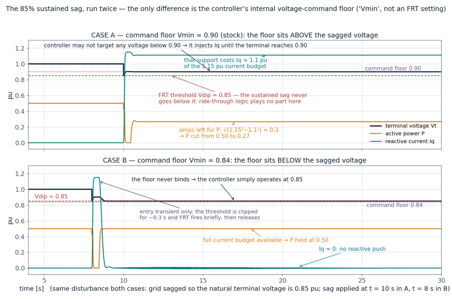
One of the Grid Code requirements in the UK, is that the inverter must withstand a sustained voltage dip of 85% for 180s. This is almost invariably the one that gives study engineers the most problems, as the inverter trips, or power collapses and is the most common problem I encounter in the day job.
Interestingly Claude picked this up as a problem with the default settings, and identified the cause without me requiring much input. The issue is conceptually simple, but not immediately obvious. The REEC controller has a parameter called Vmin, which defines the voltage floor, and that is set to 0.9, but the FRT threshold is normally set below 85%. When applying a voltage sag to 85% nominal, the inverter does not respond correctly - the Vmin (voltage floor) default sits at 0.9, which causes the power output to collapse. The solution is to set the Vmin value below the LVRT threshold. Claude picked this all up directly, with almost no input from me.
4.2 LVRT oscillation behaviour in weak grids.
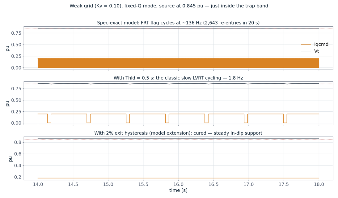
The second issue that Claude picked up confused it, as the issue is a known bug but an uncommon one - the problem of LVRT oscillation on a weak grid. LVRT oscillation is a real problem that can occur when the grid is very weak; conceptually it is a bit odd, but makes sense once you understand what is occurring. When a voltage dip is applied driving the inverter into FRT output, the reactive current injection is sufficient to drive the terminal voltage back to a healthy state. The inverter drops out of LVRT mode, the voltage falls again, and the inverter re-enters FRT and starts injecting reactive current.
The standard REEC model does not include any way to mitigate this and so it was totally confusing Claude. In fairness to Claude this is not an obvious problem - so I had to give it a bit of a nudge in the right direction, and then it realised the problem and modified the REEC system to include an LVRT Hysteresis function to overcome this type of behaviour.
5. Summary
This was starting to stretch Claude a little, and really showed how powerful it is in terms of carrying out an agentic workflow using an almost real-world application to implement a full suite of WECC controllers in PSCAD. Implementing FORTRAN directly inside PSCAD submodules made the process very easy, and as it’s ‘simple’ code, Claude handled it with no difficulties. The few issues it picked up were genuine ones and only needed a small amount of steering.
Download Technical Note 005 - WECC Storage System Modelling in PSCAD (PDF)